
In this post I show you how I manufacture the parts for the Sawppy. To build an original Sawppy Rover by Roger Cheng we need 15x15mm construction profiles made of aluminum. In addition, we will be making axles out of 8mm shafts for the bearings. Roger uses stainless steel shafts, but I think aluminum will suffice with plastic tires. Also, aluminum is easier to machine if you don’t have a lathe.
Manufacture of aluminum profiles
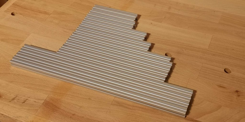
Misumi supplies the 15x15mm profiles in lengths of 2m. I have calculated the individual pieces so that I get all parts cut from 2 profiles. My cut list is here:
| profile 1 (a 2m) | profile 2 (a 2m) | ||
| 4 x 385mm | 1540mm | 3 x 245mm | 735mm |
| 1 x 245mm | 245mm | 1 x 238mm | 238mm |
| 1 x 182mm | 182mm | 1 x 182mm | 182mm |
| 2 x 161mm | 322mm | ||
| 2 x 122mm | 244mm | ||
| 2 x 117mm | 234mm | ||
| total | 1967mm | total | 1955mm |
To saw off the single pieces straight, I constructed a small cutting guide and printed it out. You can download the STL file here.
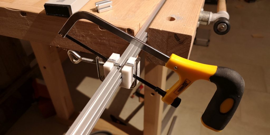
The result is straight and neatly sawed off profiles. The burrs at the ends I have processed with a file.
Manufacture the shafts
If you don’t have a lathe, making the shafts is probably the most time-consuming part of the project. Unfortunately, having the shafts made is out of proportion to the overall cost of the project. I have therefore built a small lathe from a drill and a few profiles.
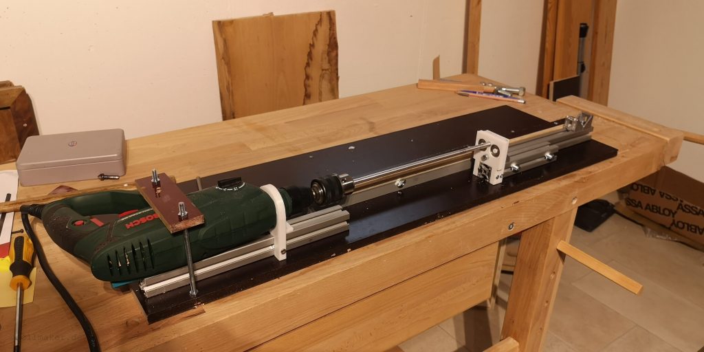
A printed holder, which is fixed on a 30x30mm profile, fixes the drill. In addition, another bolt is fixed with threaded rods. Basically, we now need to perform 4 steps.
- Twisting off the shafts to the correct dimension
- Grooving the shafts
- Twisting off to the correct length
- Filing flats for the grub screws
Twisting off the shafts to the correct dimension
I simply used sandpaper to grinding the shafts. From 80 grit to 180 grit. My shaft diameters had 0.4mm oversize for the 8mm bearings. So for a clearance fit (h7), 0.4 to 0.5mm had to go. I ended up with diameters of about 7.95mm. This allows the bearings to slide on well and the clearance is not too large.
Manufacture the grooves into the shafts
The E-clips require a diameter of 7mm. We therefore “twist off” a groove of 0.5mm depth into the shafts. There are already approaches here to do this with a Dremel. However, I came up with the idea to build a small tool with which I can make the grooves much easier and cleaner.
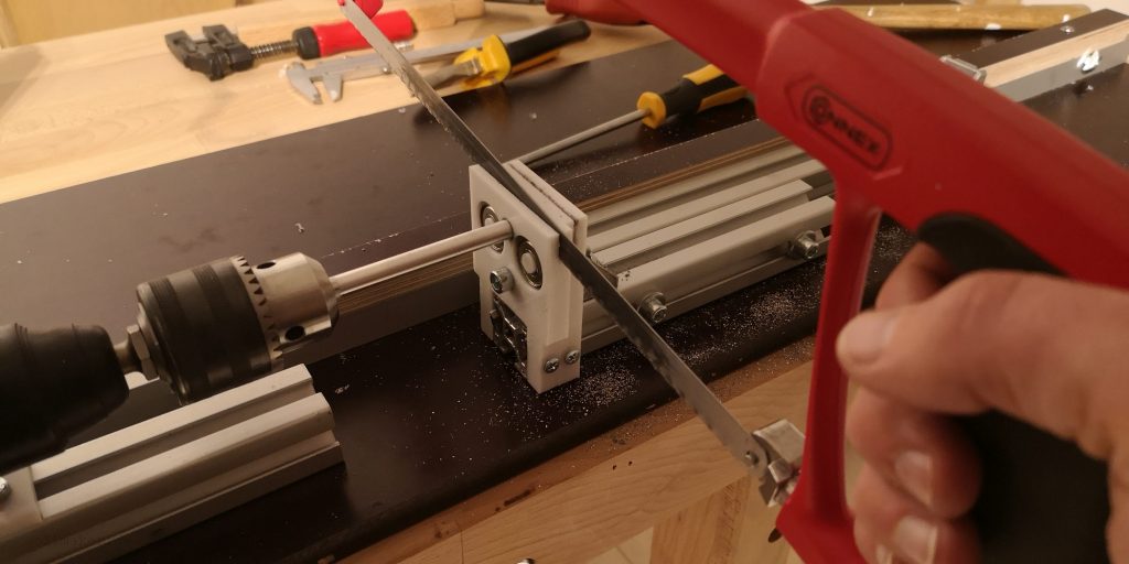
The tool consists of a printed part with a groove for a standard metal saw. This guides the saw and you get exactly straight grooves. The two bearings are installed so that the two outer rings are exactly 0.5mm below the top dead center of the shaft and can be turned. They serve as end stops to prevent sawing too deep. It is important that now, while the drill is running, we do not hold the saw still, but make slow sawing movements. This will cause the saw to wear evenly. When the groove depth of 0.5 mm is reached, this can be seen quite clearly, as the outer rings of the bearings rotate and the resistance of the saw decreases noticeably.
Now it is only a matter of placing the grooves in the right places. With a caliper gauge this is no problem. The STL file for this tool can be found here. Additionally you need two 608 ball bearings. You can use them later for the rover.
Twisting off the shafts to the correct length
The shafts are of course shortened in the same way. Also for this I have printed myself a small toll. The STL file to print yourself is here. You can see it on the top picture to the right of the groove saw tool. It’s basically the same principle, with the difference that there is an end stop for the saw. Here again from the other side.
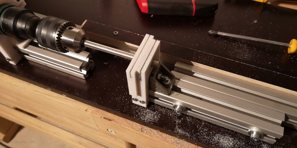
I mounted the two tools both side by side on a 30x30mm aluminum profile. This allowed me to manufacture the shafts in sequence. Always saw in the grooves first and then cut to length immediately. The aluminum profile with the tools is attached to an aluminum profile with screws. So it can be moved easily.
It was a bit of work to build the lathe, but in the end the work was worth it. And who knows…maybe I can use the lathe again for something else.
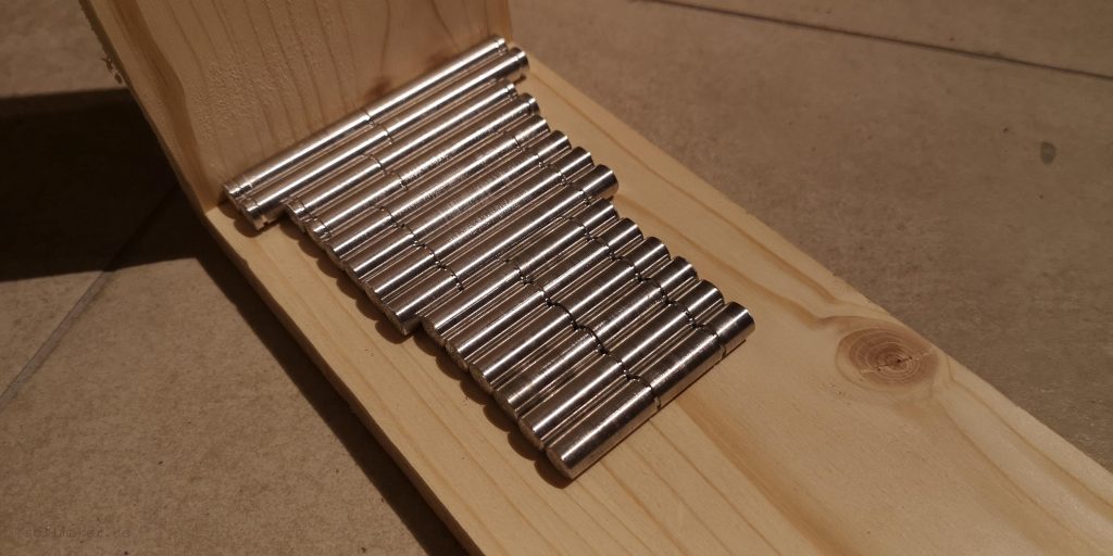
Here is the result:
Filing flats for the grub screws
To enable the motors and wheels to transmit torque to the shaft, they are fastened to the shaft with grub screws. Therefore, we file flattenings into the shafts in certain areas.
To make my life a little easier, I constructed a small tool in about 10 minutes.
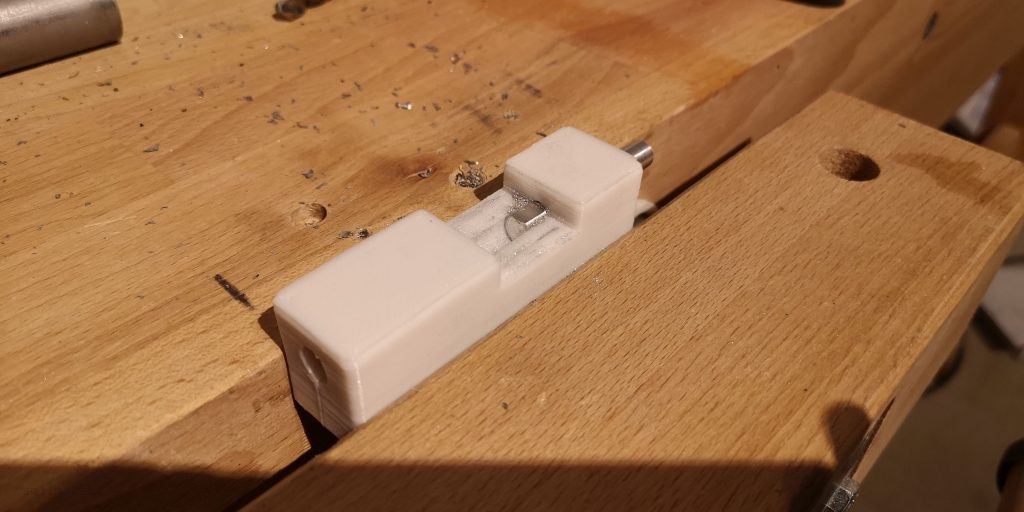
You can simply insert the shafts into the tool and clamp it in a workbench. The slot on the underside allows the shaft to be clamped. The recess provides a little guidance as to how far one may file. I ended up doing this by eye. The STL file is of course also available here.
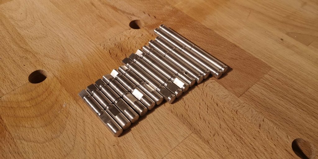
And here is the final result:
I find the Roger Cheng’s bearing concept of the Sawppy very complex for a hobbyist, but it is very professional. The grooves and E-clips mean that the axial force absorption is accommodated in a very small space. For further simplification of the Sawppy Rover, the bearing concept of the axles certainly has the most potential.