
In this article I show you how to build a smart temperature and humidity sensor by yourself. This sensor is connected to a router via WLAN and you can see the temperature and humidity of the air at all times, even when you are on the road, e.g. with your smartphone. I implement the whole thing with a WeMos D1 mini board and a DHT22 sensor. Thanks to the EASY ESP firmware, which is simply configured via the browser, not even programming is necessary. So you can configure the sensor to send the data via the cloud from ThingSpeak to your smartphone. I will explain how to do this step by step. If you want to integrate the sensor into your SmartHome, you can also do this via the MQTT message protocol, which can also be easily configured via EASY ESP. And the best thing about it: The electronic components cost only about 5€!
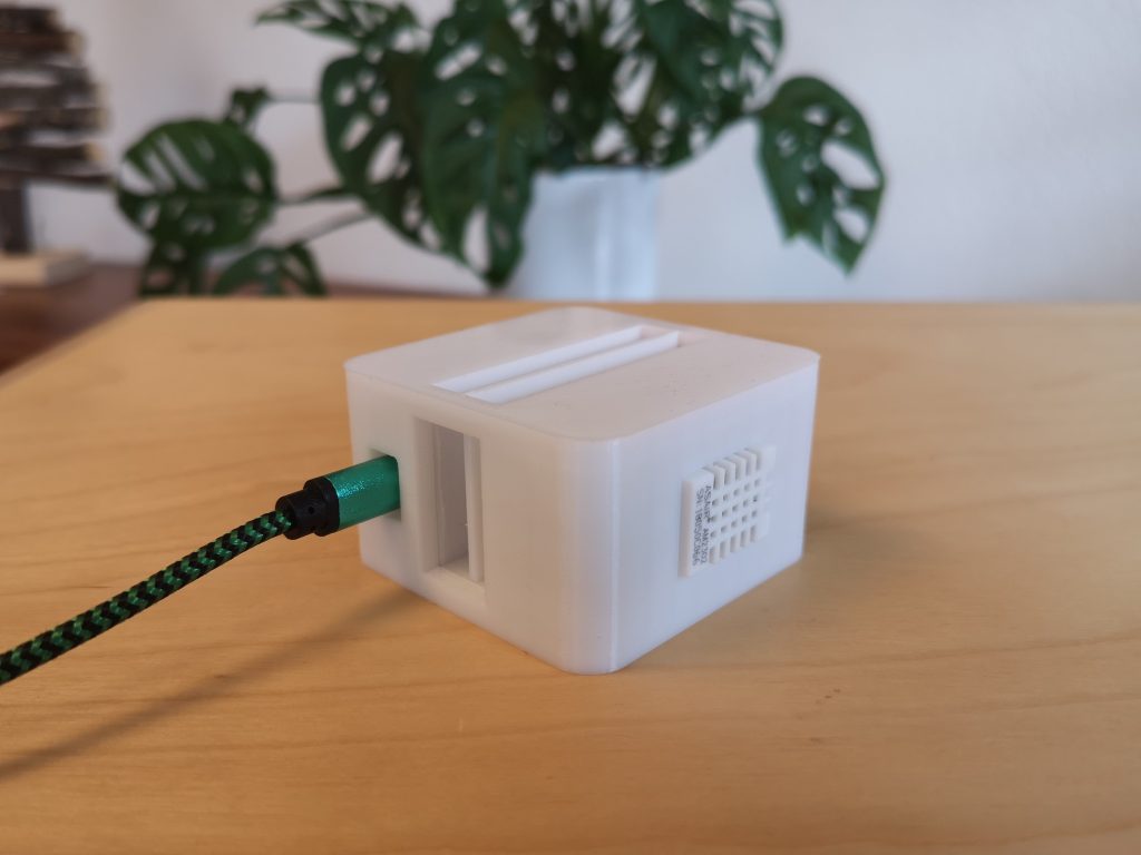
I have designed a case for my sensor that you can easily download and print. Many other cases you can find in the internet have the problem that the heat the WeMos emits has an effect on the DHT22 sensor via heat radiation or heat conduction of the case and leads to a measurement error. I have done a lot of experiments in this regard and developed a case with a heat shield that shields the heat radiation of the WeMos and prevents heat conduction from the WeMos to the DHT22 via the case.
If you don’t have a 3D printer, you can also build a case from a different material. Or you can build the whole thing on a breadboard. I show you this variant too.
1 – What is required?
[ advertising | the links marked with * are affiliate links ]
For both versions we need in any case:
- 1x WeMos D1 Mini *
- 1x Sensor DHT22 *
- 1x Micro-USB-Cable *
- 3x additional wires *
- 1x soldering iron
For version 1 (setup on a breadboard) you need additional:
- 1x Breadboard *
For version 2 (assembly in printed housing) you only need a 3D printer and the print data which you can download here.
2 – Setup version 1 on the breadboard
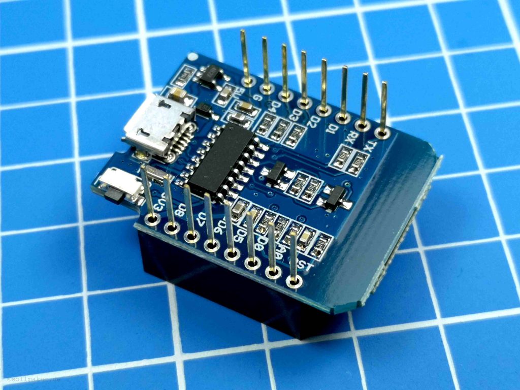
Unfortunately, it does not work without soldering. You have to solder the pin strips to the WeMos. Normally the WeMos comes with some. For our version we solder the long pin headers as shown in the picture. I will not solder mine, because I need the WeMos for variant 2 without pin headers.
After that we put everything together as shown in the picture. Note: I have here another version of the DHT22 with a slightly larger board. But it makes no difference for the assembly on the breadboard. But it does not fit into the printed case of variant 2.
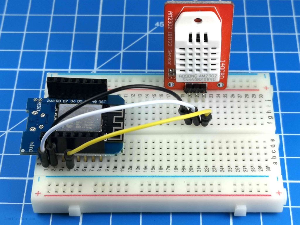
The white cable is connected to ‘5V’ at the WeMos and to ‘VCC’ at the DHT22. The black one at the WeMos is connected to Ground ‘G’ and the one at the sensor to ‘GND’ and the yellow one to ‘D3’ and ‘DAT’.
| WeMos | Kabel |
DHT22 |
| G | black | ‘-‘ or ‘GND’ |
| 5V | white | ‘+’ or ‘VCC’ |
| D3 | yellow | DAT |
Now the setup is already finished and you can jump to point 4.
3 – Construction version 2 for the housing
For version 2, or if you want to install the electronics in a separate housing, solder the wires first.
We need the WeMos, the DHT22 and the 3 wires with diameter 1.2 mm. We shorten two cables to 10 cm length and the third to 12 mm. Strip the ends for about 3 mm.
Next we desolder the angled pin header from the DHT22 sensor. This makes the whole thing smaller and fits into the housing.
Then we solder the DHT22 with the wires to the WeMos. The two lines with 10 cm come to plus and minus or ‘G’. The line with 12 cm is connected to the DAT on the sensor and to the digital input D3 on the WeMos. Here again shown in a table.
| WeMos | Leitungslänge | DHT22 |
| G | 10 cm | ‘-‘ |
| 5V | 10 cm | ‘+’ |
| D3 | 12 cm | DAT |
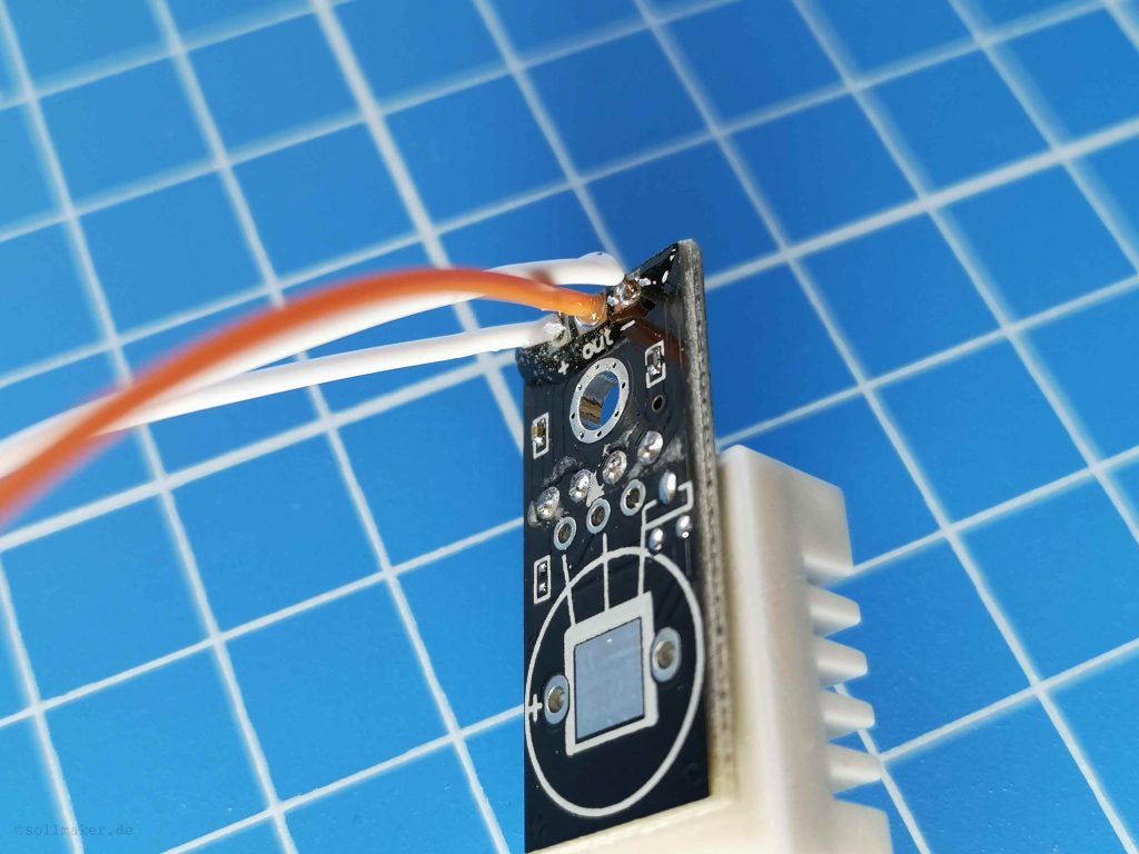
To protect the wires at the soldering points from tearing off I put some 2K glue on the soldering points. But you can also use hot glue.
We make sure that we solder the wires from the right side. Here again a picture:
Before we put the whole thing into the case I recommend you to flash the software under point 4 to see if everything works.
If everything works, it continues with the assembly:
If you want to print the case you can download and print the two files as zip-file here.
First we take the top (cover). Now we insert the sensor. To do this, first place the side with the soldering points in the groove (1.) provided for this purpose. Then press the white protective cap of the sensor through the cutout in the housing (2.).
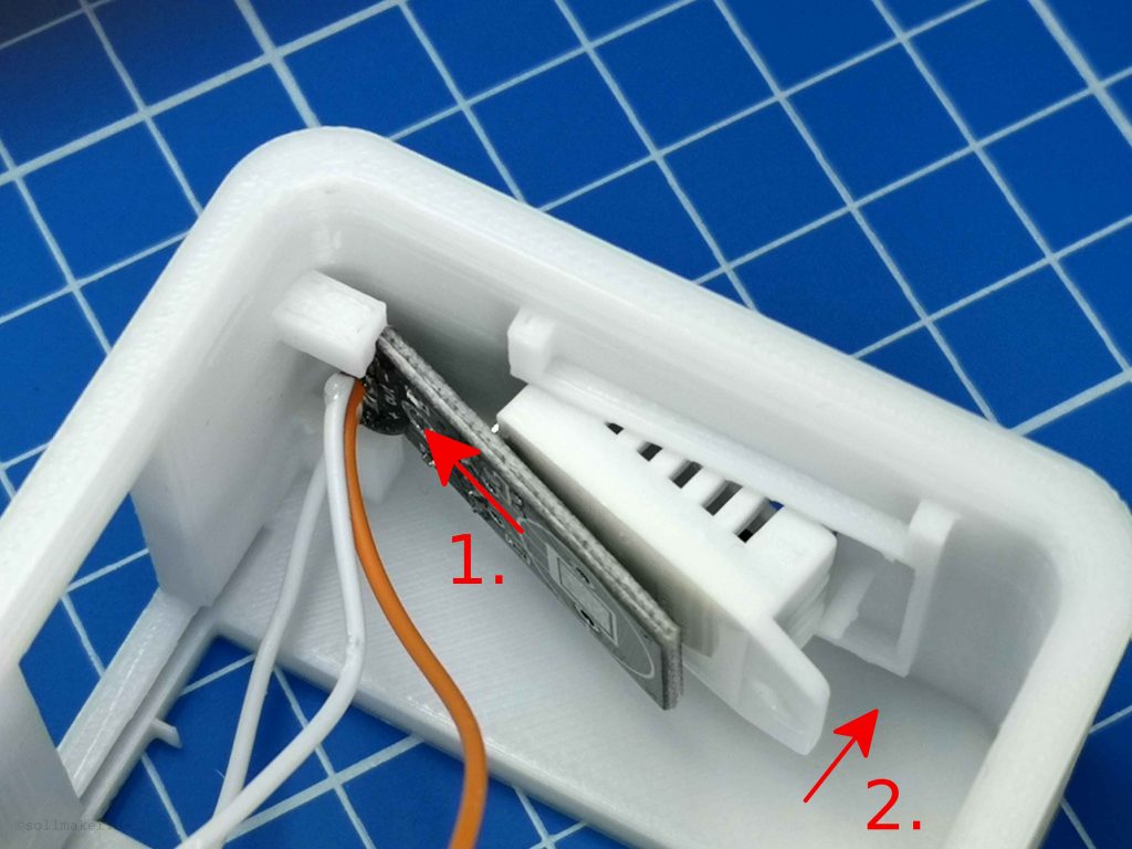
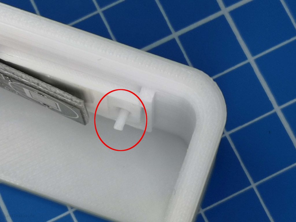
Be careful not to tear off the small pin. We need this pin for the fixing.
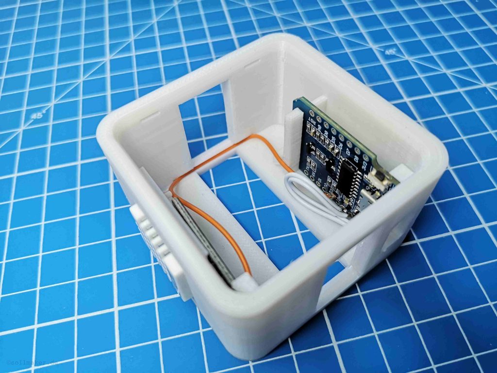
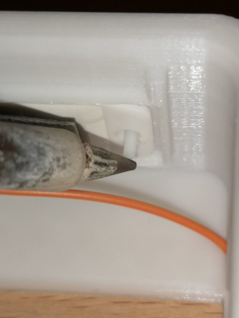
The next step is the cabling. The best thing to do first is to get the WeMos into position. Once it is in place we lay the cable for the negative pole. To do this, press it into the groove provided with a small screwdriver or another flat object.
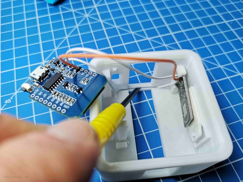
It is important that the cable disappears in the groove over the entire width of the ventilation slot so that it is not visible later. Next, we place the cable from the positive pole into the same groove.
Then it goes to the other side. Here the data line (orange in my case) is inserted into the groove in the same way as the two previous lines.
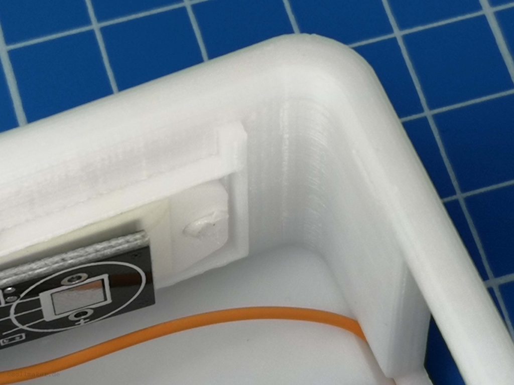
If the electronics is inserted correctly, we press the plastic pin for fixing the DHT22 briefly against the inner wall with the soldering iron.
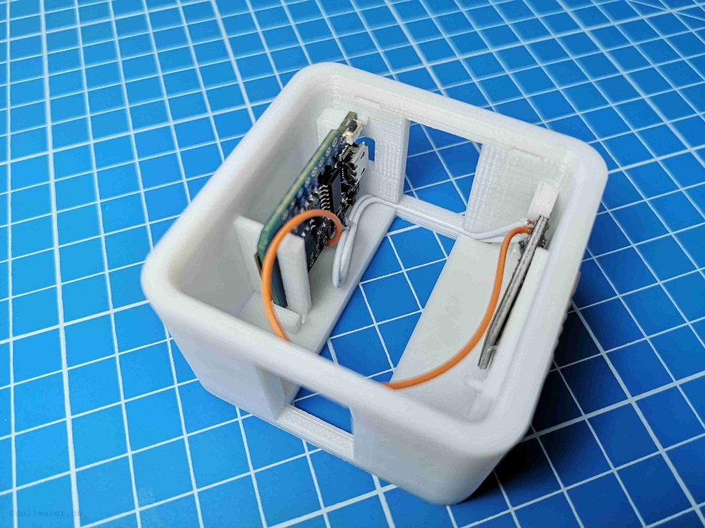
Now the sensor is fixed and we are almost done with the assembly.
Push the cables a little bit to the side, insert the lower part and snap it in.
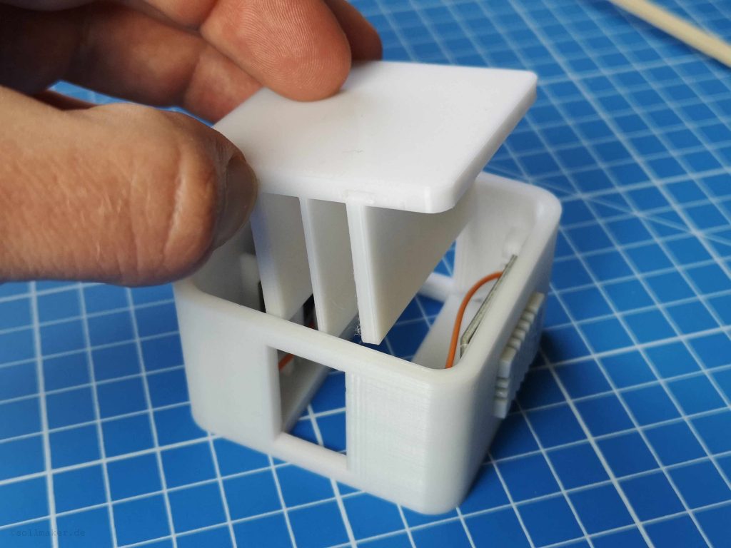
Depending on the dimensional accuracy of your parts, the snap may be tighter or looser. In case of doubt, either use a file or some glue. To get the bottom part out again I made grooves on the side next to the elevations for the snap. So you can lever out the bottom part with a flat screwdriver.
4 – ESP Easy Flashing
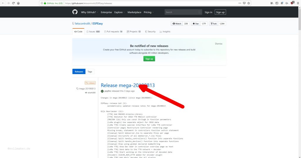
Before we build the electronics into the housing we first flash the WeMos with the software ESP Easy. If something does not work we do not have to disasseble evrithing. First we download the software ESP Easy here. For the newest version click on the top version.
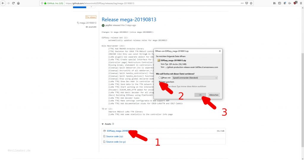
At the bottom of the page we find the zip file. Click on it and then on “Save file” and “OK”.
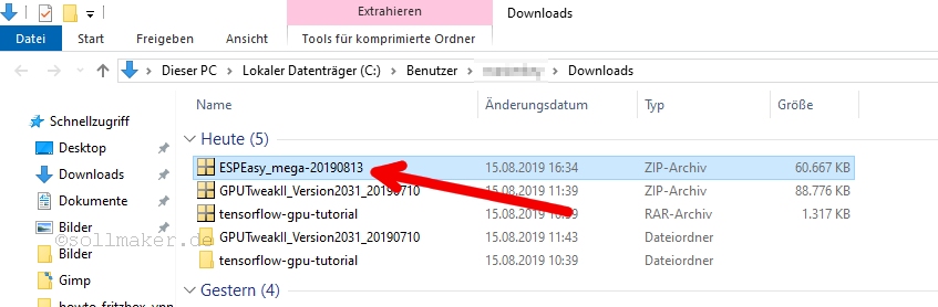
Normally you will find the zip-file in the download folder after the download. We navigate there and unzip the zip file. So right click on the file and select “Unzip”.
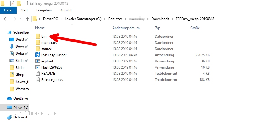
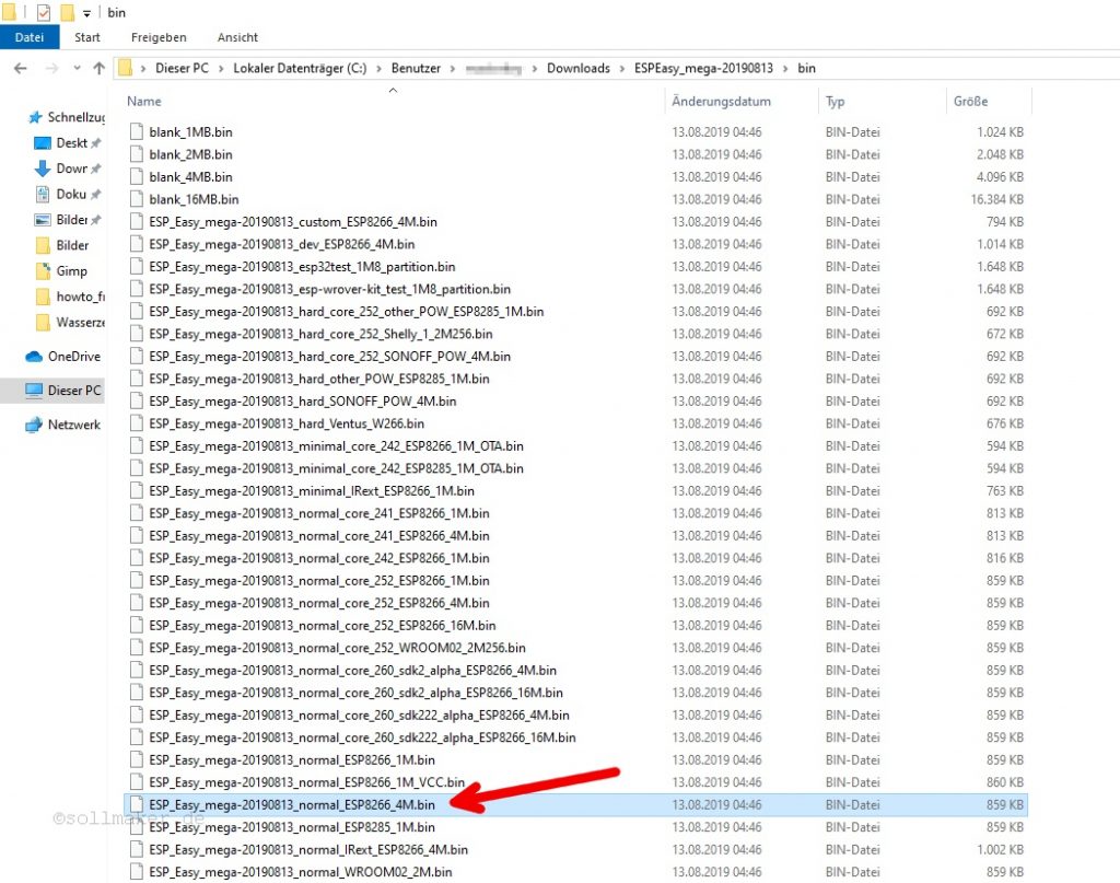
In the now created folder we find the subfolder “bin”.
 We open this and search for the file “ESP_Easy_mega_20190813_normal_ESP8266_4M.bin” (The date in the file name may be more recent). This is the firmware which we flash on the WeMos. We click with the right mouse button on this file and copy it with “copy” into the buffer.
Now we go back one folder and add this file to the main folder “ESPEasy_mega_20190813”.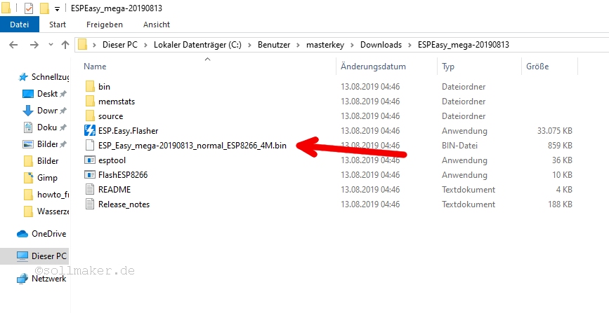
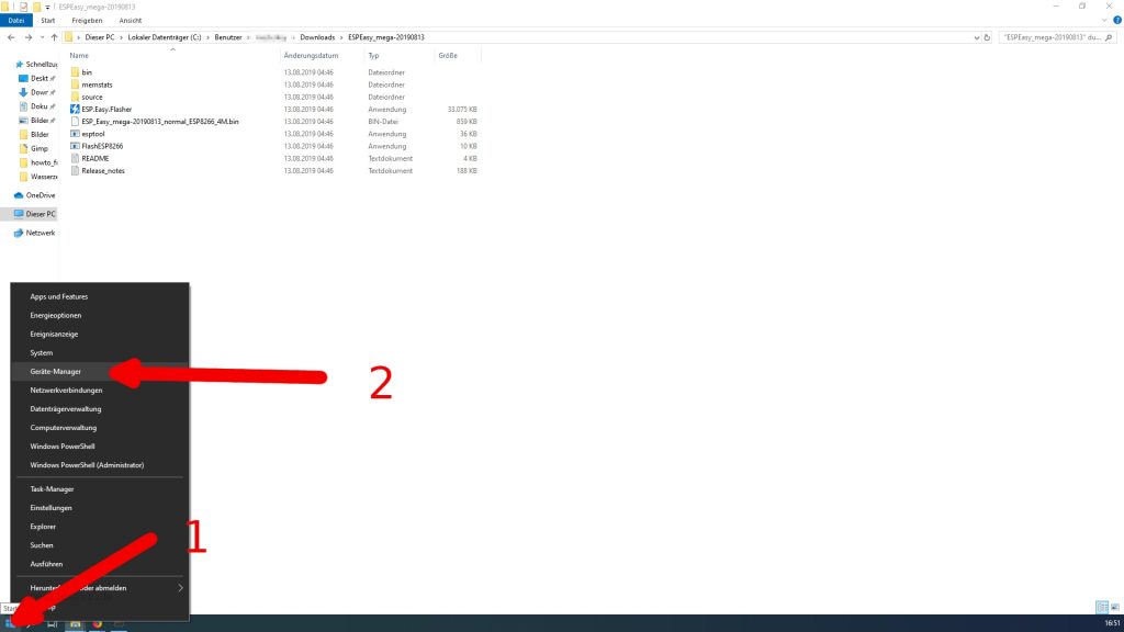
Next we have to find out which COM port the WeMos has once we have connected it to the computer. To do this, we open the device manager by right-clicking on the Windows icon and then on “Device Manager”.
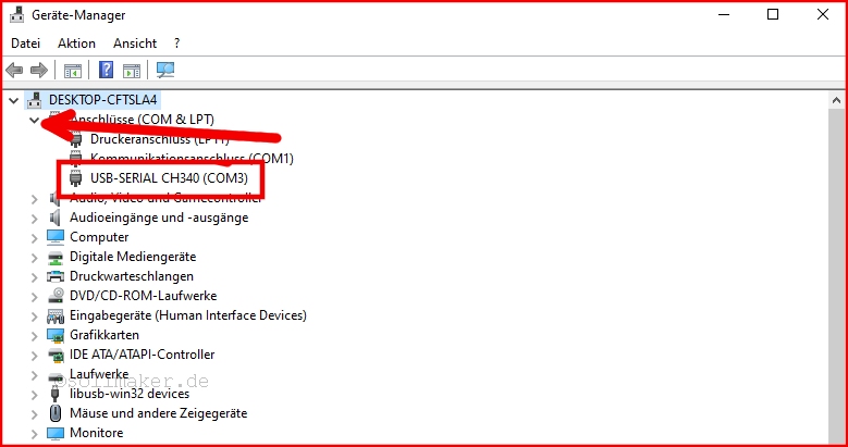
Now we expand “Ports (COM & LPT)” by clicking on the small arrow to the left.
If we now connect the WeMos to the computer a new line appears and behind it in brackets the COM port we need. In my case it is the COM3.
Now we have everything together for flashing. We go back to our ESP Easy folders and click on “FlashESP8266”. We choose the right COM port and then we click on “Flash”.
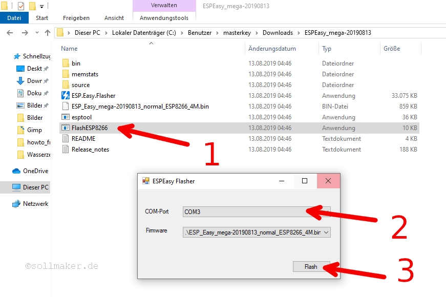
Now a window opens in which the current progress is displayed. If the WeMos is flashed we check if everything works.
For this we restart the WeMos. Either you press the small reset button on the WeMos or you unplug the WeMos and plug it in again.
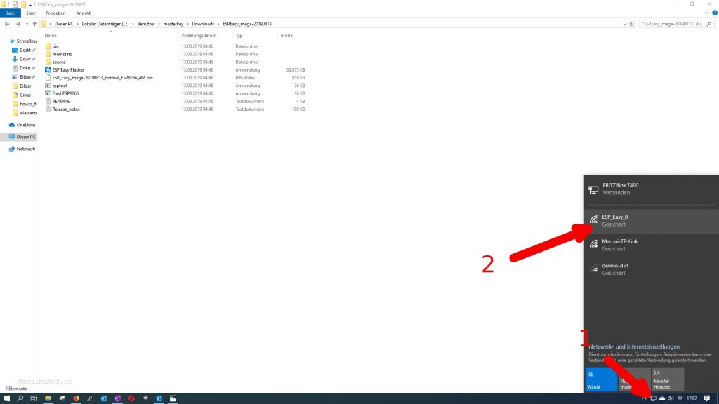
After that we can connect to the WeMos via WIFI. To do so, click on the symbol for network connections in the lower right corner. There you should see a WIFI with the SSID ESP-Easy_0. We click on it to connect to it. The password is: configesp
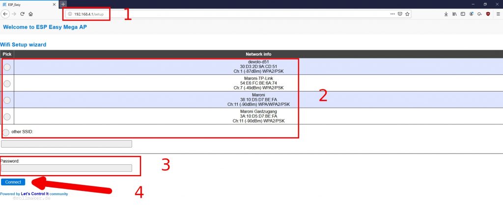
If we are connected to the WIFI of the WeMos we open the browser and enter the IP “192.168.4.1”. There we have to specify the WIFI our smart sensor should connect to later. If the WIFI is not shown, because it is not available at the place where you are, you can enter it manually under “other SSID:”. Enter the password and click on “Connect”.
Now the WeMos tries to dial into the WIFI. If the WIFI is reachable and the WeMos connects, the browser will immediately show the IP address it got in the network.
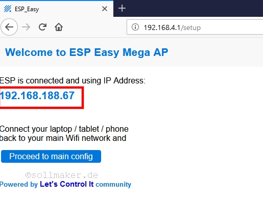
This we type in the browser and get into the main menu of the WeMos.

Before we make further settings here, we will first set up an account with Mathworks and ThingSpeak. ThingSpeak is a kind of cloud for IoT applications. Our SmartSensor will later upload the data there and we can access it from anywhere in the world.
4 – Setting up a MathWorks account
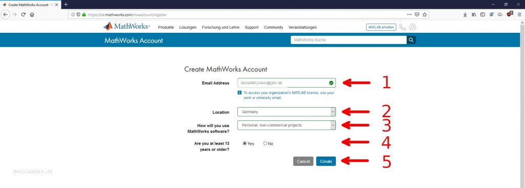
To register with ThingSpeak we first need an account with MathWorks. To do so, we go to the MathWorks homepage and click on “Create Account” at the bottom.
There we enter our e-mail address and our country. We also indicate how we use Mathworks. I use it privately and therefore select “Personal, non-commercial projects”. We also need to specify if we are at least 13 years old.
Once we have done this, we will receive an email with a link to verify the email address. We click on the link and enter the rest to set up our account.
First and last name and a password are mandatory. A User ID is optional, but you will have to think of one later when you register for ThingSpeak. Just think of something (e.g. your first name with a sequence of numbers).
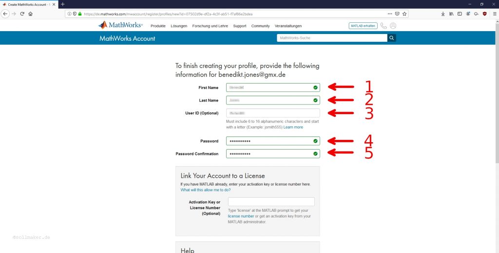
We confirm the whole thing and are done at MathWorks.
5 – Setting up ThingSpeak
With our account from MathWorks we can now sign up for ThingSpeak. To do so, we go to the ThingSpeak homepage and enter our e-mail address that we have also provided to MathWorks.
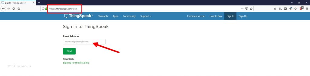
With a click on “Next” we are asked for the password. Also enter the password of MathWorks here. We end up in our account of ThingSpeak.
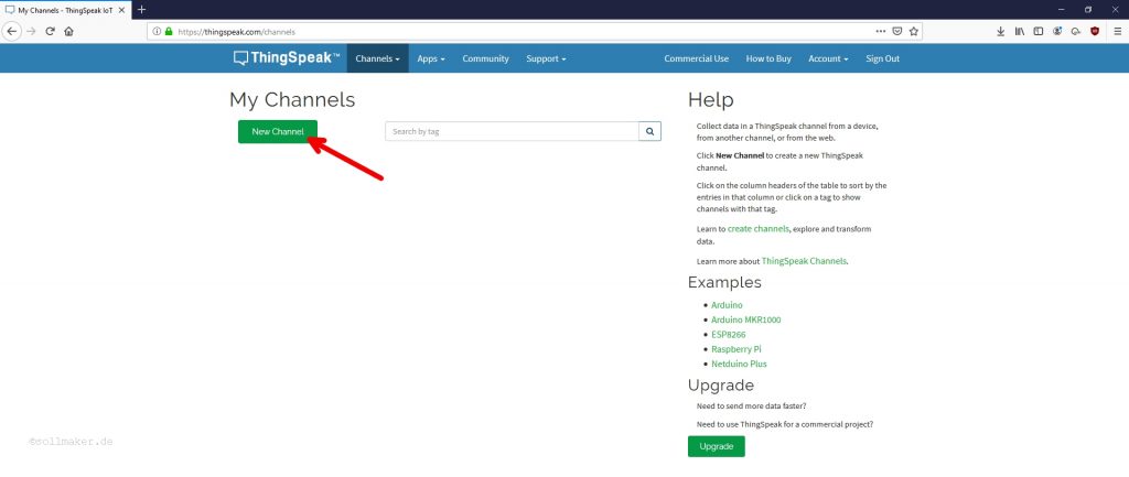
As said before we want to upload the data from the Smart Sensor to ThingSpeak later. For this we will create a channel in ThingSpeak. So we click on “New Channel”.
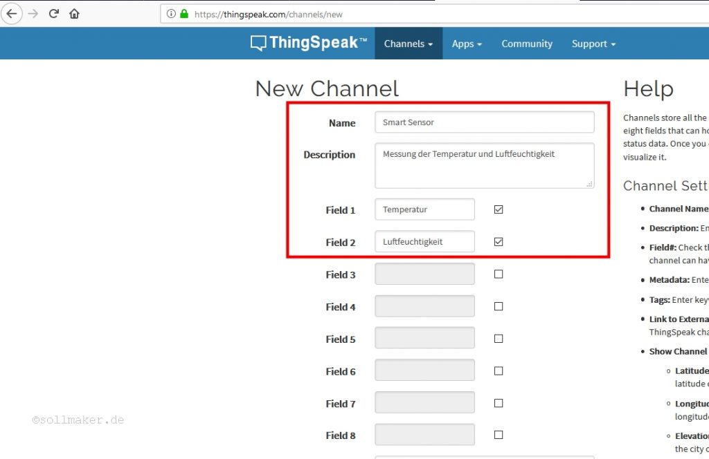
A page opens where we configure the channel. As name we enter the name of the sensor, i.e. “Smart Sensor”. Under Description we write a short text about the data that is recorded here. This is important if you have more than one sensor or if you make the channel public, so everybody knows what is going on.
Because our sensor measures temperature and humidity we activate two fields and name them accordingly. Theoretically you can connect more sensors to the WeMos and then activate more fields.
We then click on “Save Channel” below. Now we are actually already done with ThingSpeak. But we still have to connect ThingSpeak to the Smart Sensor to upload the data. And we still need a connection to download the data later. For this ThingSpeak has created unique keys by creating the channel. These we find on “API Keys”.
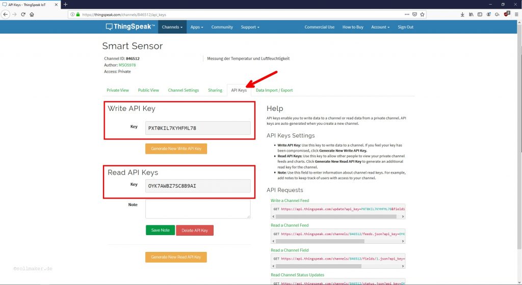
Instead of typing the keys now, we leave the browser window open and copy-paste them. Alternatively you can always log back into ThingSpeak and see what the keys to your channel are.
6 – Configuration of the WeMo with ESPEasy
Back to our actual sensor the WeMos and ESP Easy. If your WeMos still has the same IP address and you still have the ESP Easy page open – great. If not, we go to our router and check which IP address it gave to the WeMos. Then simply enter it into the browser.
The main page should then look like this: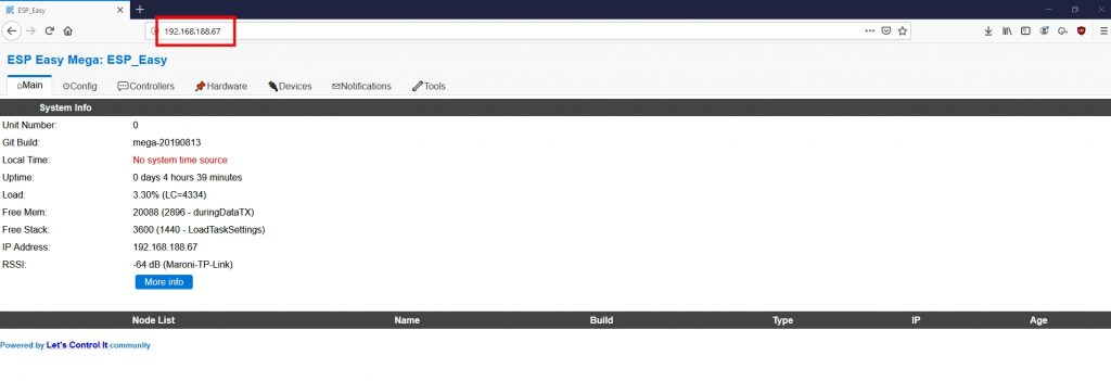
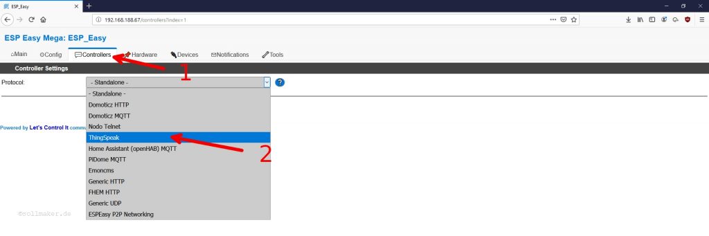
First we configure the ThingSpeak controller. To do this, we click on “Controllers” at the top of the bar and select “ThingSpeak” from the drop down menu and confirm this with “Submit”.
The window with the controller settings opens. Enter everything as shown here:
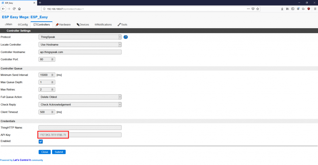
Under API Key enter the Write API Key of ThingSpeak.
You can only send data to ThingSpeak every 15 seconds. Therefore we set the “Minimum Send Interval” to 15000ms. But this is more than sufficient for our application. We confirm this again with “Submit”.
The next step is to set up the sensor. To do this, we click on “Devices” and on “Edit” in the top bar.
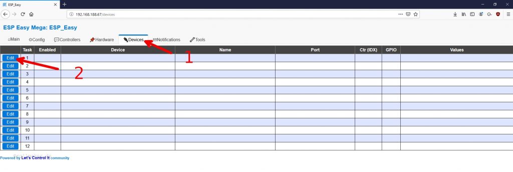
A window opens in which we can select our sensor from the drop-down menu.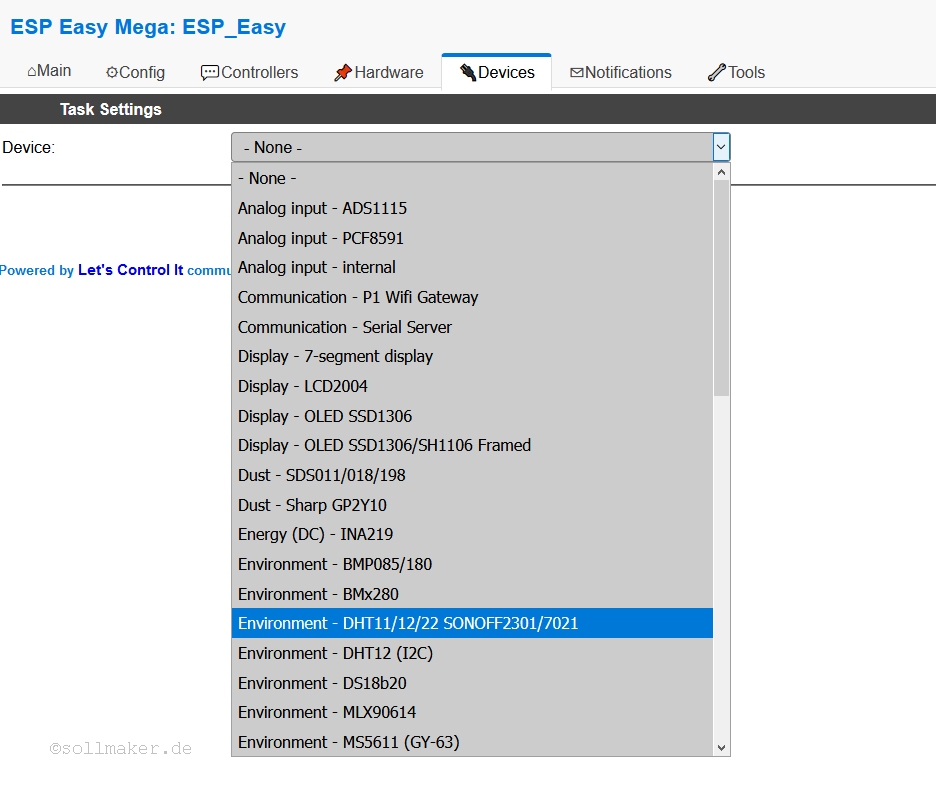
We select the DHT22 and confirm. The “Task Settings” menu opens. Here we assign a name and define on which pin of the WeMos our sensor is connected. In our case it is the pin with the name D3. Now it is important that we link the sensor with our controller. To do this we set the check mark at “Send to Controller” and set the IDX to 1, so the temperature value is set to the field with the number 1 at ThingSpeak and automatically the humidity value to the next field (field 2).
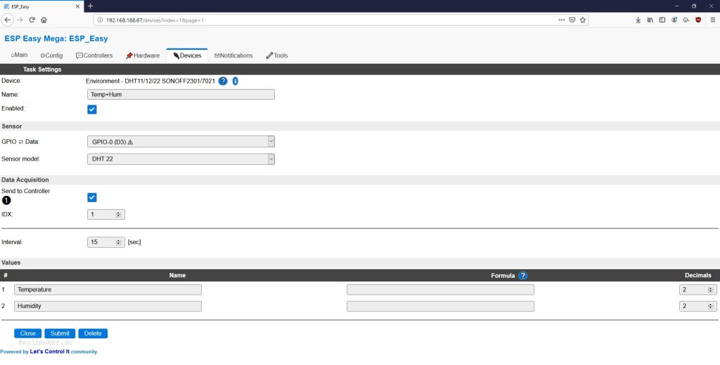
Confirm with “Submit”.
If we don’t get an error now, the first data should arrive on ThingSpeak in 15 seconds and update every 15 seconds. We can now log on to ThingSpeak from anywhere we have web access and see what the temperature and humidity is and switch on the heating, air conditioning or ventilation system accordingly.
7 – Setting up the widget on the Android smartphone
To make the whole thing a bit more comfortable, we will set up a widget on our Android smartphone in the last step.
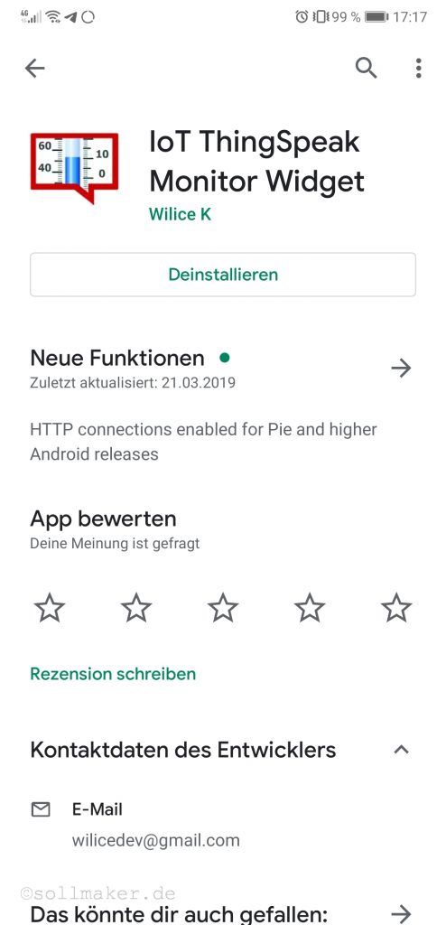
For this purpose we download the app “IoT ThingSpeak Monitor Widget” from the Google Play Store.
If we now press and hold on a free area on our screen we can select “Widgets” below. Here we scroll to the right until we find the widget.
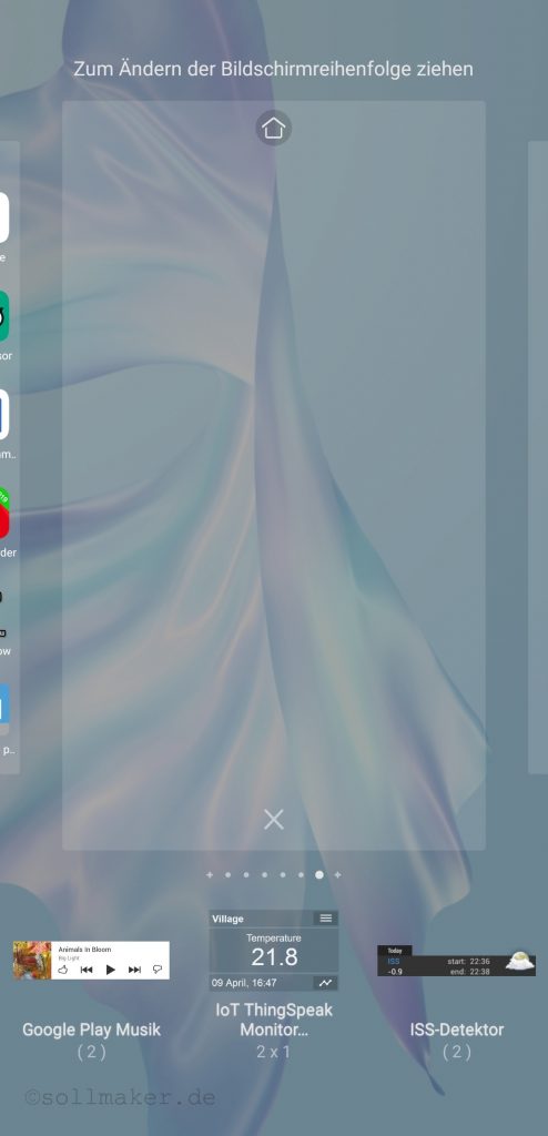
Now we drag the widget to a free area. The window for configuration will open immediately.
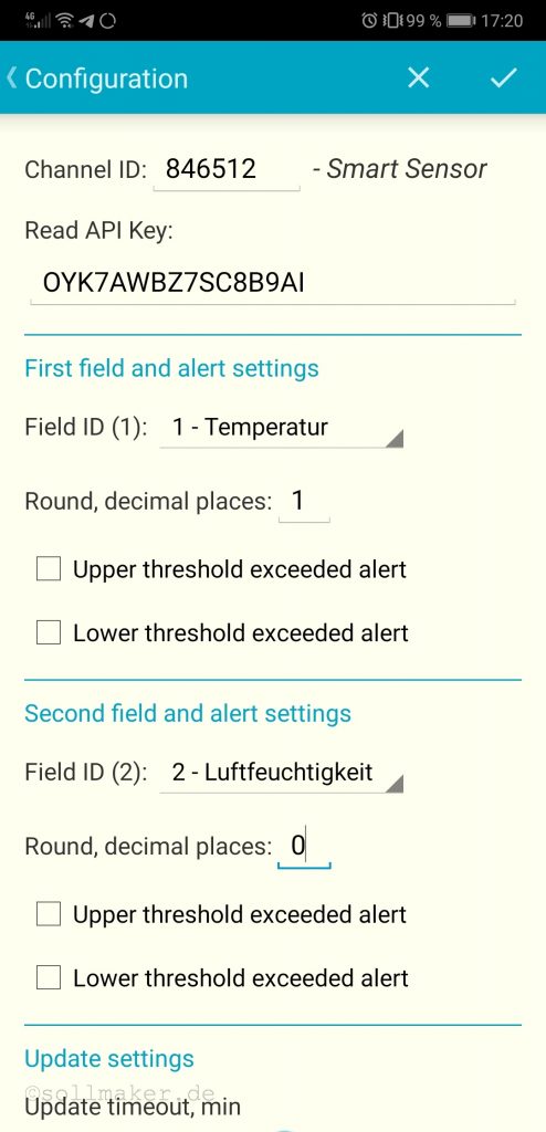
Here we enter the channel ID we have from ThingSpeak. Underneath the Read API Key, because we want to read the data from our channel.
In the first field “1 – Temperature” is automatically preselected. For the second field we select “2 – Humidity”.
If you scroll down even further you can set how often the values should be updated under “Update settings”. The default is 30 minutes. Here I choose 1 minute.
Done! Now you have built your own smart sensor and got to know some tools from the IoT world. I have been building it on a breadboard for over a year now and it runs reliably and without problems! This one, which I have built here, I will install somewhere outside, protected from the weather.